Several times in the past my ME stopped in the middle of a slew and put out the dreaded beep-beep-beep sound. This usually occurred while imaging objects high in the eastern sky under CCDAutoPilot3 control - slewing to and from high altitude focus stars. Turning the ME off, then back on, then finding Home, always worked to get me out of the situation. But of course I wanted to find out why this was happening and if possible, correct it.
For the record: The usual first bit of advice one always seems to get from the Bisque forum or Yahoo blogs to any complaint about the ME's performance is, "Make sure the RA and Dec worm gear tension screws are backed off." I have ALWAYS done that religiously. I have also reduced the slew speed - even though this is Arizona not Alaska. My mount is, and always has been, in excellent balance - and the load on it is relatively light. See: Equipment.html
I discovered that at least one other ME owner has had this same experience. In this other ME the 50 conductor cable was apparently pushing on the RA motor (and/or its cables) and causing it to react as though the mount had hit an obstruction - thus the stopping and beeping. Also this other ME had rubbed off the insulation (exposing bare copper) from the aux power cable that runs from the Adapter panel up through the hole in the RA axis.
I found on a page on the Bisque website (since removed) that there is now a heat-sink guard installed in ME mounts that prevents wires from getting snagged on the heat sink. I wondered if I had one in my ME.
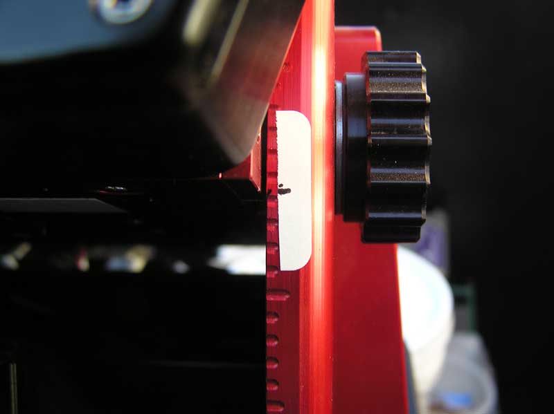
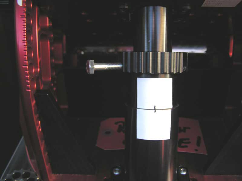
In order to check on what was going on inside my mount, I cranked up the polar axis and removed the west side panel. Before twisting the polar axis adjustment wheel I placed three small labels on the mount to show where the correct altitude position was located. This was suggested in the above Bisque instruction page. The next two images below show these initial Latitude position labels. The reason I removed the west side panel is because no electronic boards or connectors are attached to it (as they are on the east-side panel).
Figures 1 and 2. Polar axis positions labeled so as to be able to return to the original alignment.
These markings enabled me to get back to correct alignment after I had looked inside the mount.
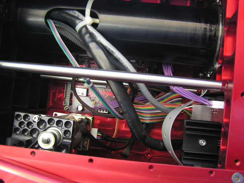
The view shown below is what I saw immediately after taking off the west-side panel of my ME. The first thing I noticed was that the RA motor pivots up and down just a bit as you back off the RA worm gear tension screw. It is spring mounted. I was very grateful to find that my ME has one of the new heat-sink guards installed. The RA motor is at the lower left. The heat-sink guard is the curved gray piece at the lower right.
Figure 3. My first look inside.
There was no loss of insulation or damage to the aux power cable where it is wire-tied to the 50 conductor bundle as it enters the oval hole in the RA axis at the top of the above image. The aux power cable does seem to be pretty squashed by the wire-tie, but this is probably OK. This photo was taken horizontally - looking straight into the mount from the west side. It shows the oval opening in the RA axis pointing out straight toward the west. The Dec axis and counterweight were over my left shoulder as I took this. Notice that the 26 conductor multicolored ribbon cable (that comes from the Adapter board on the extreme right) meanders pretty far forward into the mount before bending back to terminate on the right edge of the controller board. Notice also that the two covered RA motor cables go outward toward the right from the motor and pass behind the black 50 conductor bundle and also the ribbon cable.
I observed that, as the the Dec axis (with its counterweight) swung down from the west, through the vertical plane and then upward on the east side of the mount, the 50 conductor bundle did contact the RA motor leads. It also compressed the multicolored 26 conductor ribbon cable toward the east side panel (and into the main controller board). This ribbon cable also pushed on the RA motor cables which lead to the upper right hand corner of the controller board. Whether that contact and movement was enough to cause the slew failures or not is a question. I do know that the failures I experienced almost always occurred when the scope was pointing in the eastern sky, close to the meridian. This position is when the Dec axis is getting into the final position (counterweight horizontally out to the east).
My cure was :
1. I inserted a new additional wire tie about 3 inches down from the original one that binds the 50 conductor bundle to the aux power cable. This helps to keep the 50 conductor bundle back away from the RA motor.
2. The 26 conductor multicolored ribbon cable goes between two fixed terminals (the Adapter panel and the main controller board) and therefore does not need to move as the RA axis rotates. So I pushed it back to the right into the south east corner of the mount so that it could not contact the other cables that DO have to move. I hope it stays put there, immobile. I added nothing in the way of wire-ties or anything else to keep it there however.
3. I moved the RA motor cables slightly forward (to the left) so as to minimize their opportunity of being tugged on by the moving 50 conductor bundle and Dec motor cables. I did nothing to keep them there and they may migrate back to the right with time and usage of the mount. I hope they do not.
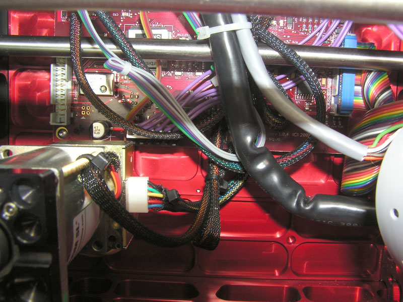
My final arrangement is shown below. The new wire-tie is at the top of this photo. It seems logical to me that the cable bundles that do not have to move (the six blue power supply wires, the RA motor cables, and the 26 conductor multicolored ribbon) should be kept as far away as possible from the rest of the cables that DO have to move. Compare the image below with the initial view shown above.
Figure 4. Wiring locations after my rearrangement.
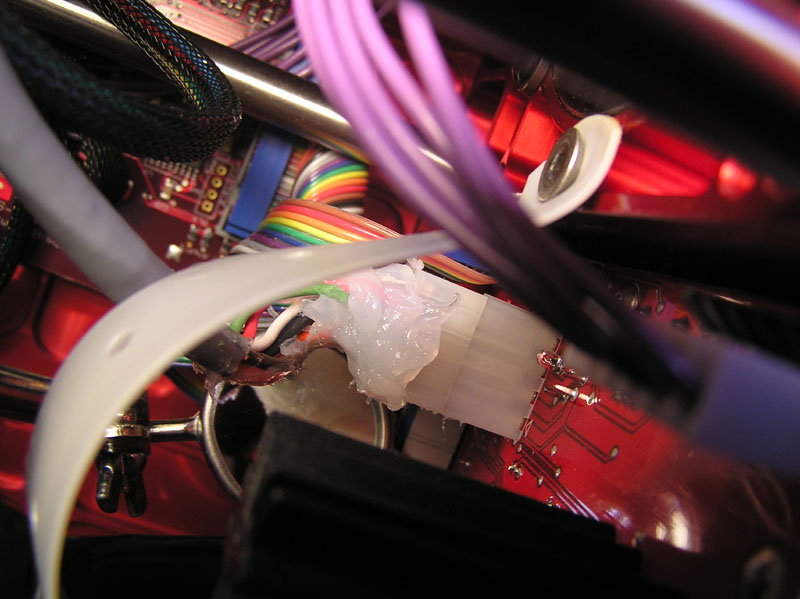
Because of some reports of wires breaking off from the Molex through the mount power cable connectors on the Adapter Panels of some other MEs, and Steve Bisque's suggestion to add a bit of clear silicone there for physical support and stability, I have done that as a preventative measure. The result is not pretty, but it should vastly reduce possible metal fatigue in the wire to pin joints in that connector.
Figure 5. Glob of silicone added for physical support of the wires entering the Molex connector. (The dentist's mirror was not left in the mount.)
Whether or not these changes will permanently eliminate the slew failures is yet to be determined. But I did not replace three of those 'hidden' tiny Phillips head screws, so I can now remove the west side panel without ruining the polar alignment. It will be easy to check inside from time to time. I have had a couple of years of flawless performance from the ME since this was done. So I am very encouraged.
Don Scott
Return to the Equipment description